Candy Dispenser
Role: Product Designer
Skills: Design Sketching, Rapid Prototyping, CAD (Fusion 360), 3D Printing
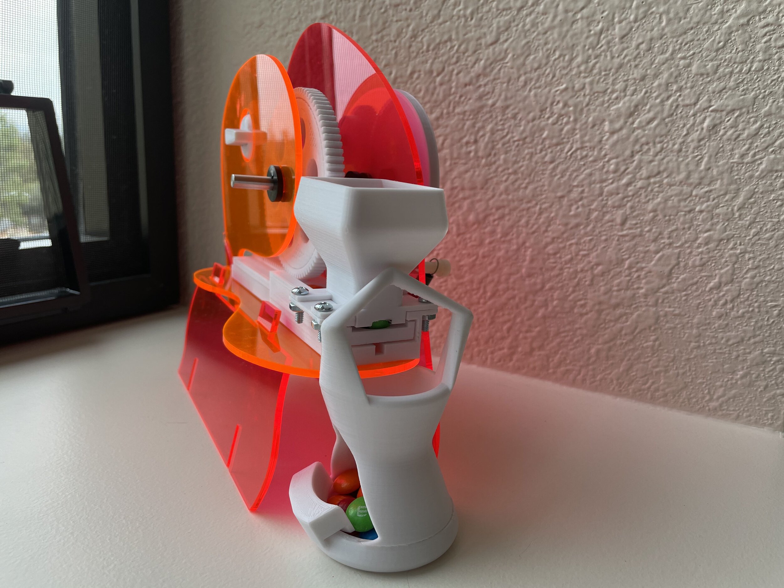
Overview: Created rotary dial M&M dispenser made from a 3D printed mechanism, manufactured operational components, and Glow-Edge Acrylic supports.


Mechanism Ideation
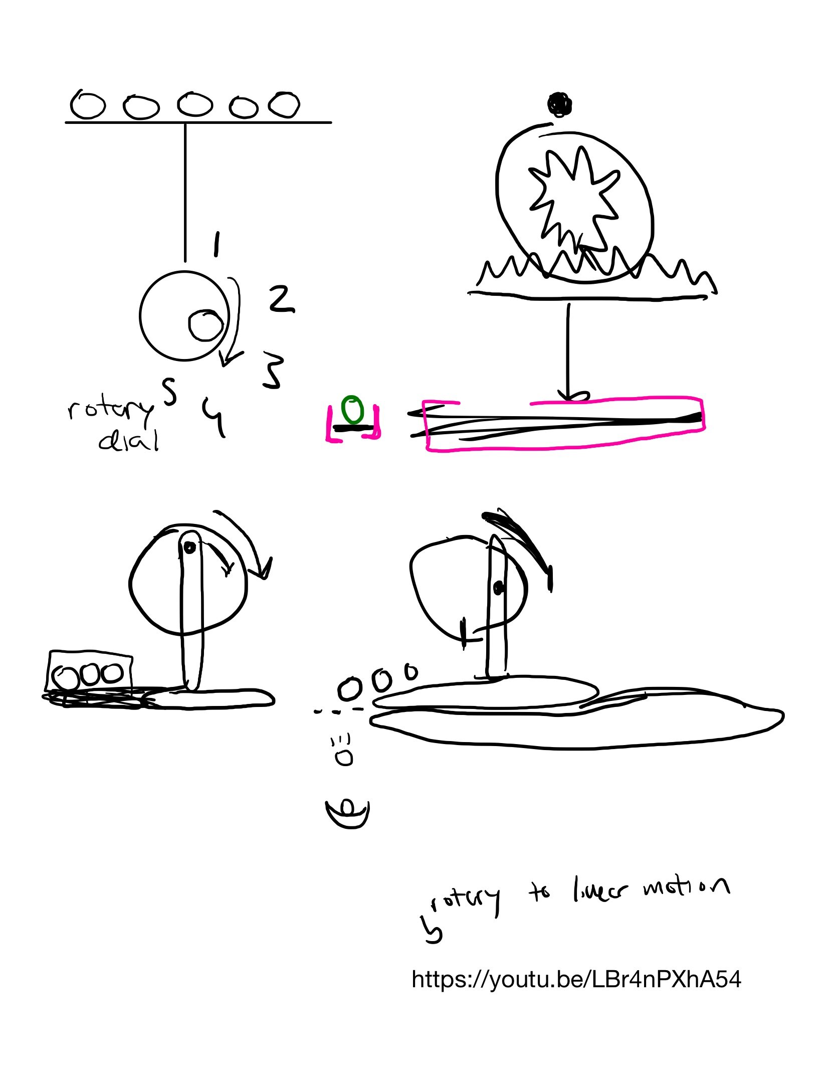
Going into this project, I knew I wanted to translate rotational motion to linear motion so that the amount a user moves a dial would determine the number of M&Ms the machine dispenses. I also wanted to incorporate a spring that would set the mechanism back to resting position once the user let go of the dial and got their M&Ms.
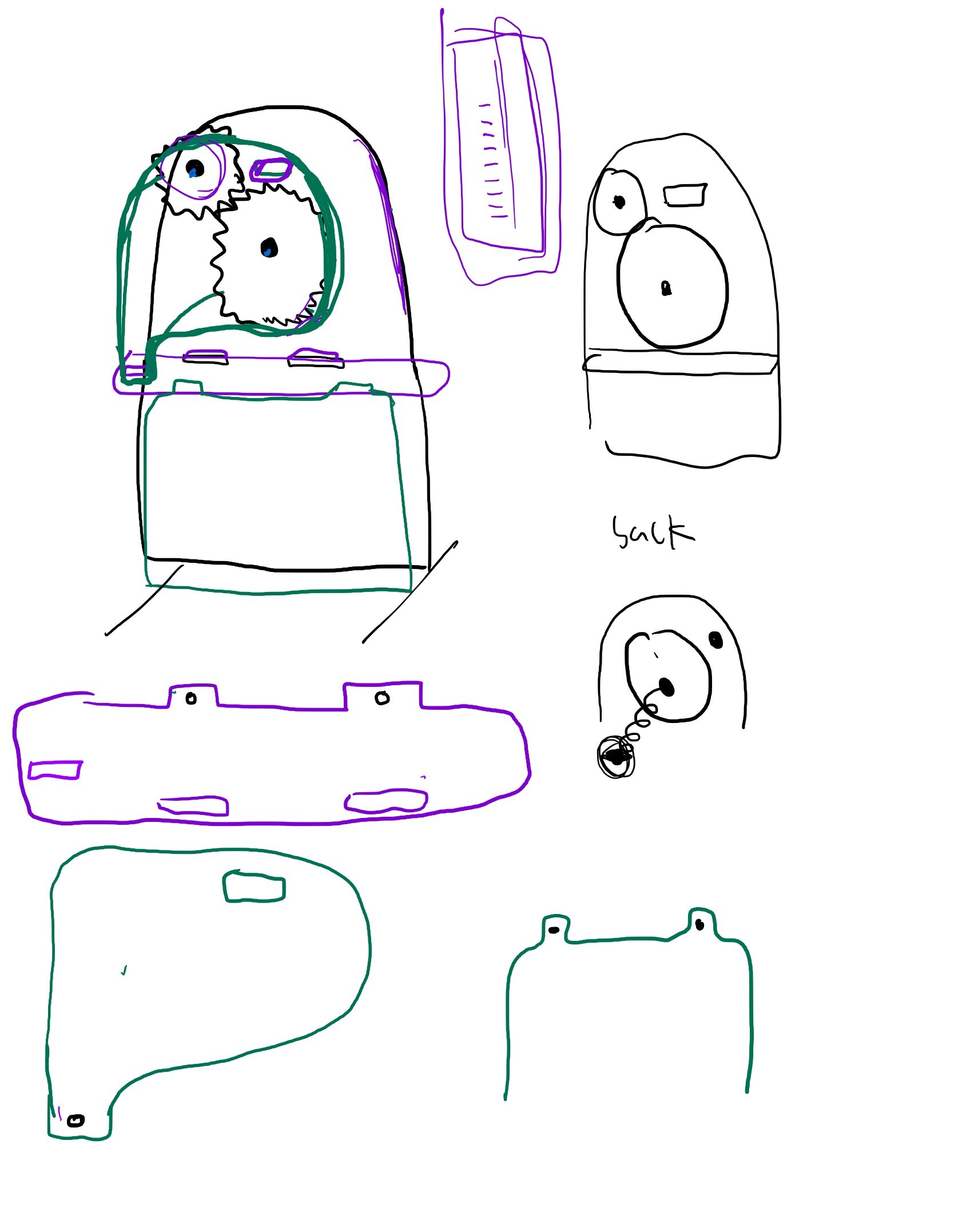
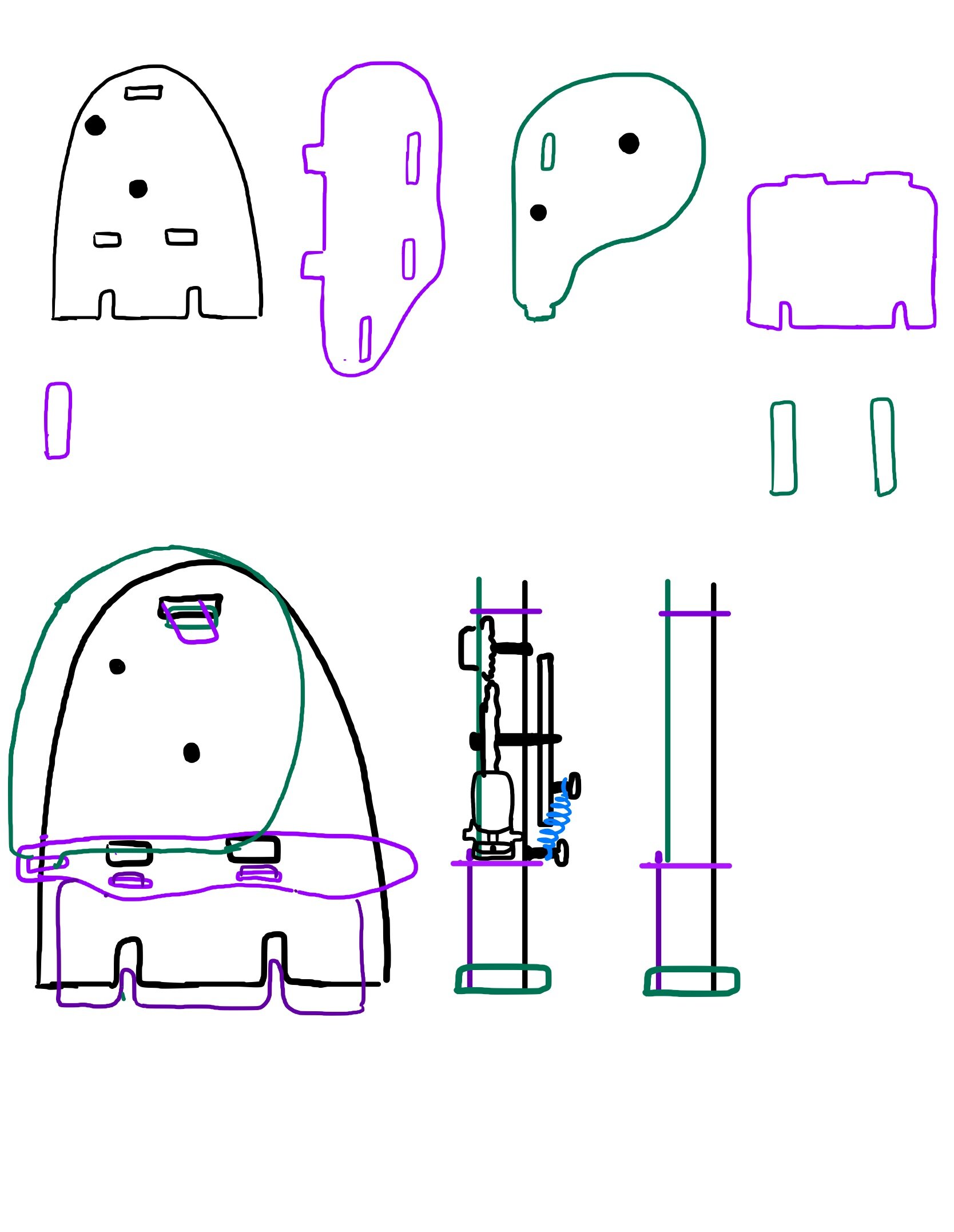
Below is a progression of my brainstorming session and initial concept sketches.


Rapid Prototyping

Prototype 1
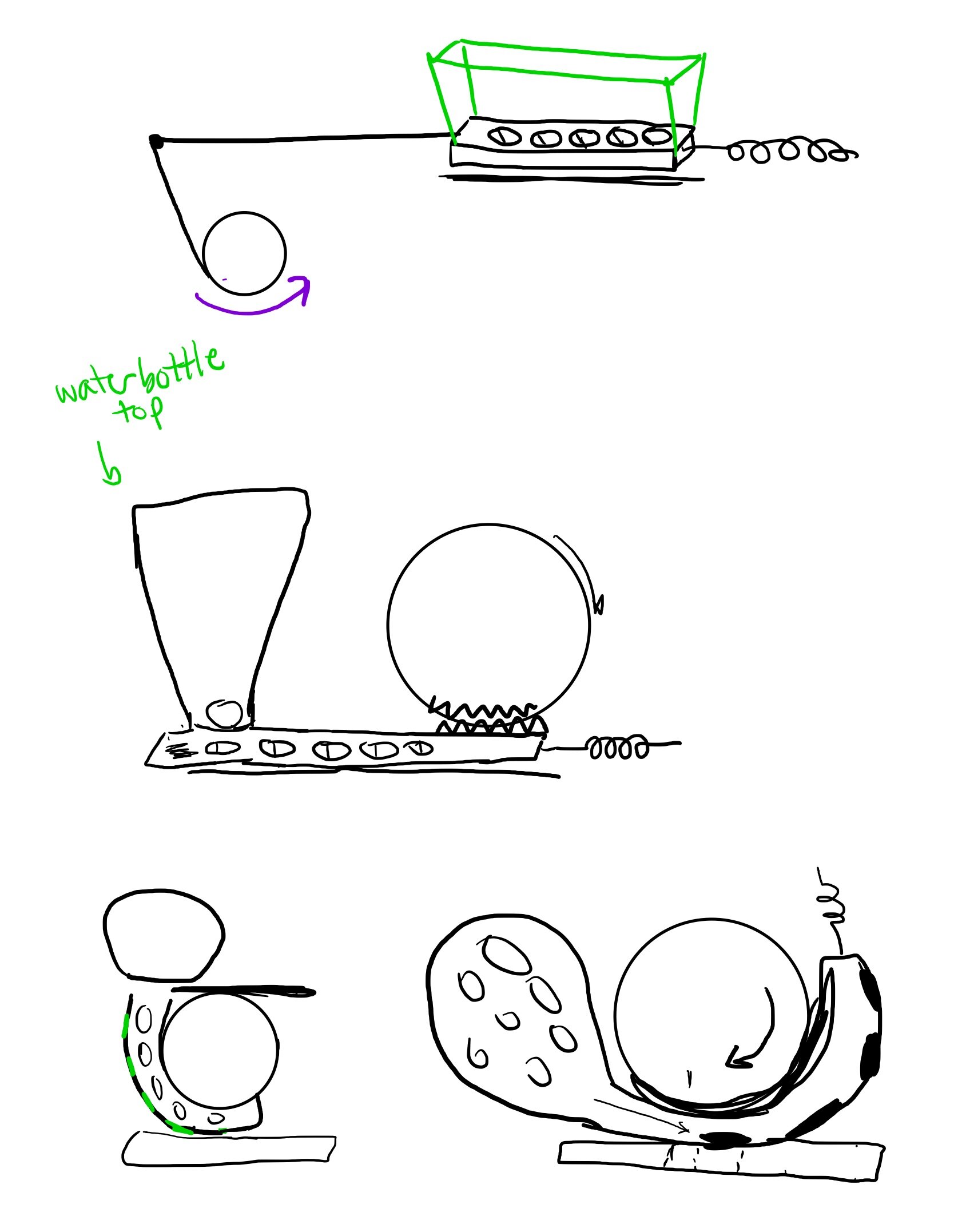
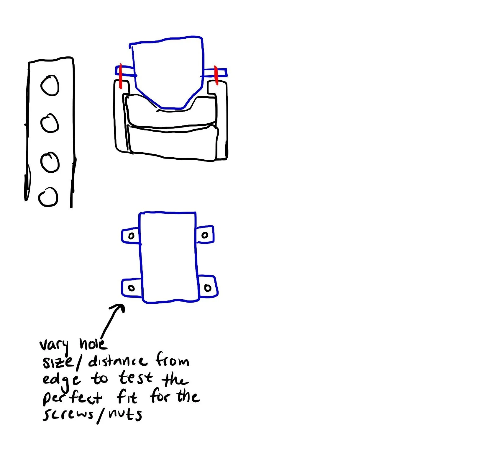
This prototype was all about measuring. I translated the length of 5 M&M-sized holes to locations on a circle, and used the circumference of that circle to determine the the total length of a platform that has a gear rack attached to it, with the idea that as a gear-ed dial rotates, the M&M platform will move away from a floor and M&M’s will fall through the holes. I used string in replace of gears for this mechanism.

Prototype 2
For this version, I played around with the placement of each component in an attempt to decrease the width of the dispenser. I also increased the thickness of the dial to keep the string from falling off of its edges. This prototype includes a spring-powered lever arm that resets the mechanism, which I surrendered in the final product. I ended up using a spring wheel that shares the gear’s axle and allows the spring to extend in a linear motion as the dial is used.
CAD Prototyping & 3D Prints
Below is a slideshow documenting the iterations made to the digitally modeled and printed prototypes. Click on each image for a brief description of each mechanism, the stage of the process and the purpose they served.

Documentation of Iteration #1 CAD measurements.

Iteration #1. At this point, I did not connect the gear rack to the platform in Fusion so I printed them separately in hopes to glue them together. The thickness of the platform was not large enough.
Sketch for Iteration #2. I wanted to include a trough that would store M&Ms and allow the platform to act as a floor for the trough.

Printing the second prototype using the Ender 3D Pro.

Iteration #1. Unfortunately the ridges of the platform did not have a large enough tolerance and would not fit into the lip of the floor.

Each component that was printed during Iteration #2. I ended up using the same gear printed in this version as there was no issue with it.

Comments about Iteration #2 and how to fix it.

Iteration #3, with a gear train comprised of a rack attacked to the M&M platform, a large gear that translates rotational to linear motion, and a user operated dial.

CAD rendering of trough.

CAD rendering of dial.

CAD rendering of floor, platform, and trough assembled.

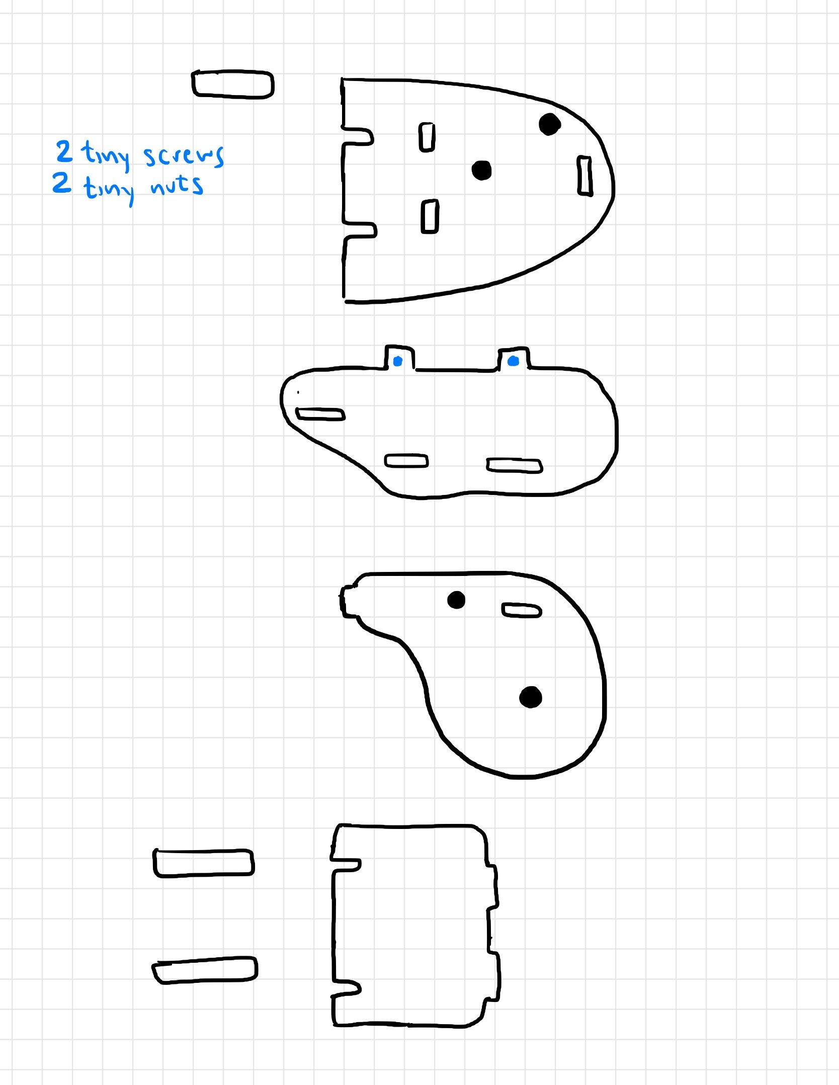
Sketches and floor plan for the spring wheel that shares the same axle as the main gear in contact with the gear rack.

Varying sizes of the spring wheel.
Support Concept Sketches
Because the mechanism is very industrial, I wanted the supports to feel lively and fun. I designed the components of the structure with natural, bouncy curvature using Illustrator and laser cut them out of Glow-Edge pink and orange Acrylic. Below is a slideshow of the initial sketches and ideas for the design.


Rapid Prototyping

Prototype 1
I started devising a plan for the supports by cutting out space in cardboard to see how all of the pieces fit and interact with each other.

Prototype 2
After I gauged the piece’s positions relative to each other, I sketched out and made Prototype 2 out of foam core, as opposed to the first prototype that was made without an idea of the structure.

Prototype 3
Before laser cutting the prototype out of acrylic (which was a limited and expensive material!) I laser cut out of cardboard to make sure the illustrator file properly translated to the dimensions and relative placements of the mechanism.